How a Marktplaats find sparks doubt about accuracy.
© 2025 MarME — Marco’s Measurement Equipment
Background
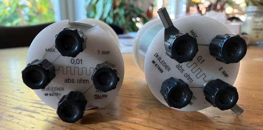
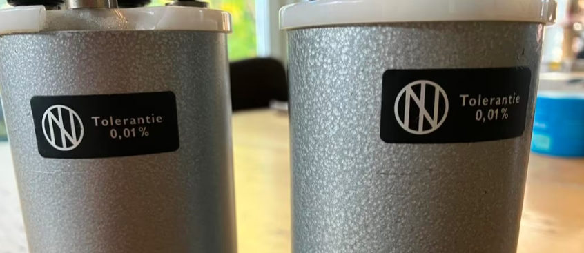
I recently found two vintage Bleeker precision resistors on Marktplaats: a 0.1 Ω ±0.01% and a 0.01 Ω ±0.01% model. After some doubt I had to get them, Bleeker to me feels like a long gone pinnacle of Dutch engineering. Verifying a 0.01% tolerance at such low resistance values is challenging — an error of just 1 mV at 1 A already represents 100 ppm.
My best DMM is a HP/Keysight 34401A. Its 4-wire (Kelvin) mode is ideal for low-resistance work, but the specified 4-wire accuracy is still insufficient to directly confirm 100 ppm deviation. To go further, I used a classic combination of current reversal (also known as offset-compensated ohms). A next step will be to do a ratio measurement between 10 mΩ and 100 mΩ standards. This cancels thermal EMFs and removes the DMM’s gain error from the ratio.
Measurement setup
- Resistors: Bleeker 0.01 Ω and 0.1 Ω (four-terminal types)
- Current source: using a lab power supply for ≈ 1 A DC (≈10 mV across 10 mΩ; 100 mV across 100 mΩ)
- Metering: Using my Brymen BM867s and my 34401A to measure the voltage over the resistor (Brymen in DC mV range) and the current through it (34401A).
With current reversal, the resistance and EMF are obtained as:
$$
R = \frac{V_{+} – V_{-}}{I_{+} – I_{-}}
$$
$$
V_{\mathrm{EMF}} = \frac{V_{+} + V_{-}}{2}
$$
This is the well-known offset-compensated or current-reversal technique to suppress thermal EMFs in low-resistance measurements. Keithley and Tektronix explicitly derive this relationship as R = (VM+ − VM−) / (2 I) when |I+| = |I−|. See the references below for exact source material.
Initial results (separate I and V measurement)
Using the 34401A for current and the Brymen DMM for voltage, after current reversal:
| Resistor | R (measured) | Deviation | Thermal EMF | Comment |
|---|---|---|---|---|
| 0.1 Ω | 0.100 007 50 Ω | +75.0 ppm | ≈ −31 µV | Excellent agreement |
| 0.01 Ω | 0.010 000 65 Ω | +65.2 ppm | ≈ +11 µV | Within spec |
With this configuration the (k = 1) uncertainty is dominated by the current measurement (±mA on ≈1–2 A) and by voltage resolution and noise — typically several hundred ppm. The results are compatible with the 0.01% spec, though not a rigorous verification yet.
Improving accuracy: the ratio method
To reduce systematic error, both resistors can be connected in series and the voltage across each measured with the same DMM and on the same DC range. Because both readings share the same gain and calibration, the meter’s scale error cancels in the ratio:
ratio = ΔV0.1Ω / ΔV10mΩ ⇒ R0.1Ω = ratio × R10mΩ (assigned)
The current itself does not need to be known — it is identical through both resistors. Remaining uncertainty arises from the noise and resolution of the voltage readings (Type A) and from the assigned uncertainty of the 10 mΩ reference. This “bridge-like” approach is standard practice for low-resistance comparison. The only issue in my current setup is the stability of the current source. Since I’m using a regular lab power supply, the current is fluctuating too much to measure both resistors with the same DMM.
Next up
Stable current source
Both for this and other measurement I want to design and build my own stable current source. Preferably one that can be set to different currents.
Practical notes
- 34401A settings: fixed 100 mV DC range, AutoZero ON, NPLC = 10–100, 10–20 samples per polarity
- Thermal EMF: keep wiring and connectors symmetric; averaging + current reversal cancels most offsets
- Self-heating: 10 mΩ @ 1 A = 10 mW; 100 mΩ @ 1 A = 100 mW — allow stabilization or use short duty cycles
- Range matching: ensure both 10 mV and 100 mV readings use the same DMM range (34401A 100 mV DC)
Conclusion
With current reversal these two Bleeker standards show remarkably close agreement — deviations around only a few × 10⁻⁵ Ω (tens of ppm), outstanding for decades-old components. With my current setup I can’t reach the accuracy to verify the 0.01% specification of these beautifull old resistors. A very stable current source could be of great help here, a good topic for a next insights blog.
References
- Keithley / Tektronix – Low Level Measurements Handbook (7th ed.), Section 3 “Low Resistance Measurements”. Describes offset-compensation / current-reversal method and derivation of R = (VM+ − VM−) / (2 I). PDF
- Tektronix / Keithley Blog – “Low Resistance Measurement with a SourceMeter: Do I use Current Reversal, Offset Compensation or Delta Mode measurement methods?” (explicit derivation and use case). Link
- Keysight 34401A User’s Guide – supports 2-wire and 4-wire resistance; recommends 4-wire for best accuracy in low-resistance work. PDF
- Megger Ltd. – A Guide to Low Resistance Testing, overview of 4-wire technique and reversible test current practice. PDF
- JCGM 100:2008 – Guide to the Expression of Uncertainty in Measurement (GUM), Sections 5 and E.3 (uncertainty propagation and ratio measurements). Link
Equipment: HP / Keysight 34401A, Bleeker 10 mΩ & 100 mΩ standards, 4-wire Kelvin leads.
Leave a Reply