An overview of the GPSDO project
Building a GPS-Disciplined Oscillator (GPSDO)
Background and inspiration
A GPS-Disciplined Oscillator combines a local high-stability oscillator (typically an OCXO) with the long-term accuracy of GPS time.
Over the years, many excellent DIY versions have appeared; the two I learned the most from were:
- Lars Walenius’ “DIY GPSDO with Arduino and 1 ns Resolution TIC” on the EEVblog forum — a classic, deeply detailed thread that explains the time-interval counter principle, PI-control loop, and the importance of filtering GPS jitter.
- Paul’s DIY Blogs – GPSDO Version 4 — a more modern, compact variant with lessons learned from Lars’ design, especially around thermal management and supply isolation.
My build followed Lars’ architecture most closely.
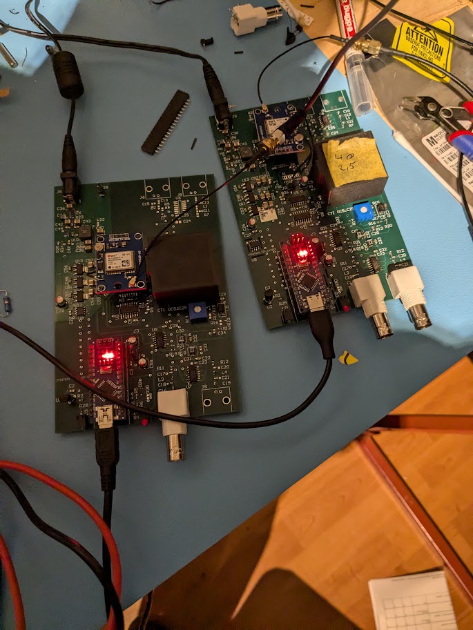
Hardware overview
- OCXO: a NOS Isotemp oven-controlled oscillator sourced from AliExpress.
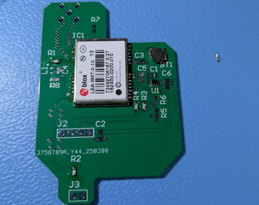
To help with temperature stability, I designed and 3-D printed a small plastic thermal cover that prevents rapid cooling when the ambient changes. - GPS receiver: u-blox LEA-M8T timing module, chosen for its 1 PPS stability and access to raw timing data.
- Controller: Arduino Nano, running firmware based on Lars’ control algorithm (time-interval counter with proportional-integral loop).
- Power architecture: every functional block has its own 5 V LDO regulator to minimize coupling:
- one for the GPS,
- one for the OCXO,
- one for the Arduino and DAC/PWM section.
- Reference and tuning circuit:
For the OCXO tuning voltage, I use a REF5050 precision 5.000 V reference feeding a fine trimming potentiometer.
The control loop then applies a correction of a few tens of millivolts via two combined PWM outputs from the Arduino, summed and filtered to achieve ≈16-bit effective resolution.
This allows microvolt-level steering of the OCXO frequency.
Loop architecture
Tbd.
Measurement results
tbd.
Power-supply noise and thermal tests.
tbd.
Integration with your lab reference system
tbd.
© 2025 MarME — Marco’s Measurement Equipment
Leave a Reply